

Views: 0 Author: Site Editor Publish Time: 2026-07-03 Origin: Site


Selecting the wrong pump for an industrial application creates a ripple effect of serious problems. It rarely just reduces system efficiency. It leads directly to premature mechanical failure, severe process bottlenecks, and highly disruptive unplanned downtime. Both pump categories effectively move fluids through complex piping networks. However, their underlying mechanics rely on vastly different engineering principles. Positive displacement and kinetic energy systems remain highly specialized. They handle entirely different fluid behaviors and varying system parameters. This guide strips away confusing marketing claims. We provide a clear, evidence-based framework for evaluating a gear pump against a centrifugal alternative. You will learn to compare them based on fluid viscosity, pressure requirements, and long-term maintenance realities. By the end, you can confidently match the right technology to your specific operational needs.
Viscosity is the primary filter: Centrifugal pumps excel with water-like fluids; gear pumps are required for highly viscous fluids (oils, resins, syrups).
Flow vs. Pressure behavior: A gear pump maintains constant flow regardless of system pressure; a centrifugal pump’s flow rate drops as system pressure (head) increases.
Implementation Risk: Gear pumps require strict over-pressure protection (relief valves) to prevent catastrophic failure if deadheaded; centrifugal pumps are highly susceptible to cavitation if improperly primed.
A positive displacement system relies on precise mechanical movements to trap and move fluids. It uses interlocking gears to repeatedly enclose a fixed volume of liquid. As the gears rotate, they physically force this trapped fluid out through the discharge port. The meshing action of the gear teeth prevents the fluid from flowing backward. This creates a highly reliable and predictable transfer mechanism.
The operational reality of this design is straightforward but unforgiving. Flow remains directly proportional to rotational speed (RPM). Because it forces fluid movement mechanically, the pump cannot simply stop if downstream pressure spikes. It will continue to build pressure relentlessly. If a valve closes downstream, the system will pressurize until a component breaks or a relief valve opens. You must install robust over-pressure protection to safely operate these systems.
Kinetic energy systems operate on an entirely different physical principle. They use a rotating impeller to impart high velocity to the incoming fluid. The fluid accelerates outward from the impeller blades. A surrounding casing, known as a volute or diffuser, then captures this fast-moving liquid. The casing rapidly slows the fluid down. This sudden decrease in velocity converts the kinetic energy into physical pressure.
This kinetic conversion process makes the operational reality highly dependent on system resistance. The pump cannot force fluid against an infinite barrier. If you close a downstream valve, the flow rate drops to zero. The impeller will simply churn the fluid in place at its maximum head pressure. While this will eventually boil the fluid due to friction, it will not immediately rupture the piping. Flow volume constantly shifts as system resistance fluctuates.
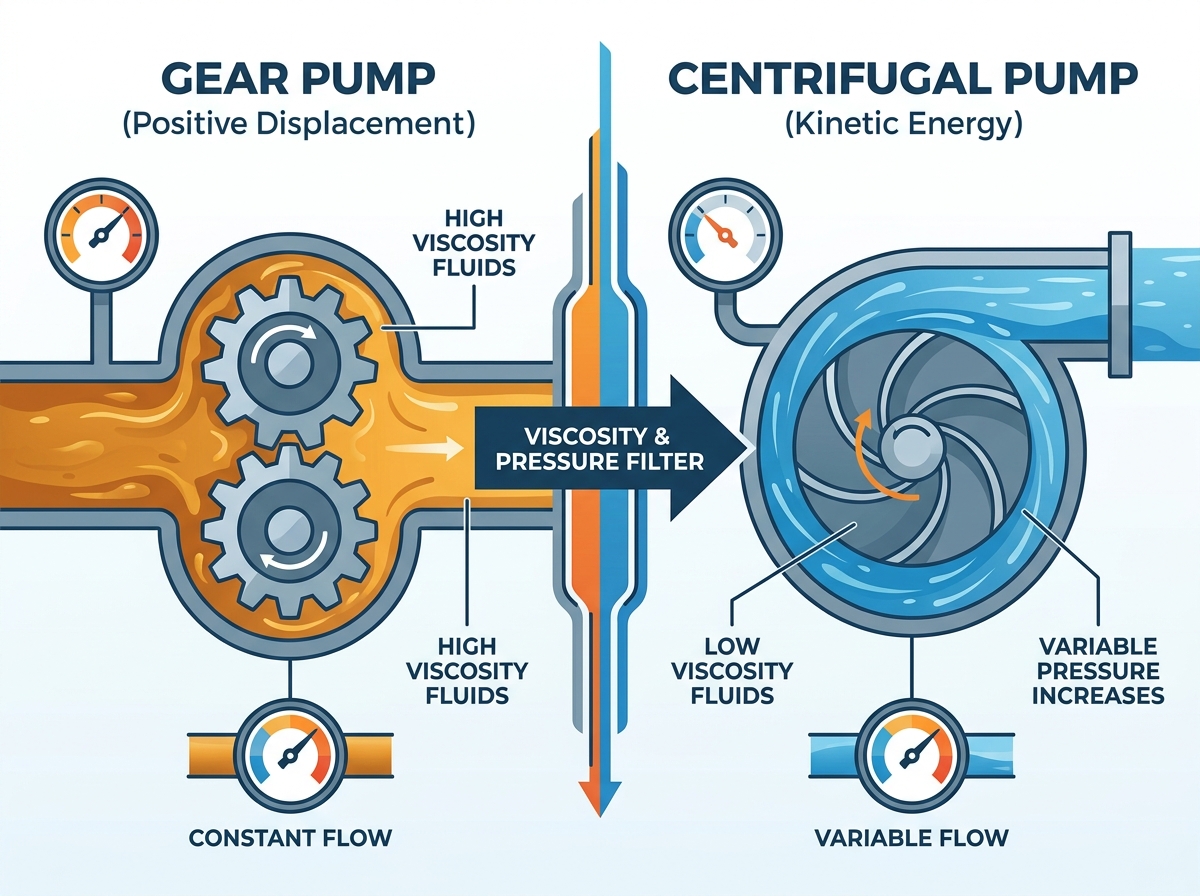
Engineers consistently look at viscosity first when choosing between these two technologies. Centrifugal limits become very apparent as fluids get thicker. They remain highly efficient for fluids under 100 cSt (centistokes), such as water or light solvents. However, as viscosity increases, internal impeller friction spikes exponentially. This friction drastically destroys mechanical efficiency and increases power consumption. The pump simply cannot spin fast enough to impart the necessary kinetic energy into a thick, sticky fluid.
Conversely, a gear pump thrives on high viscosity. Thicker fluids actually improve the machine's overall volumetric efficiency. They act as a natural sealant. Thick fluids better seal the microscopic internal clearances between the gear teeth and the casing walls. This prevents fluid from slipping backward during operation. When pumping heavy oils, resins, or syrups, this positive displacement method easily outperforms kinetic alternatives.
Fluid purity plays a massive role in pump longevity. Centrifugal designs hold a significant advantage when handling dirty fluids. Engineers often equip them with open or semi-open impeller designs. These specific designs can easily handle suspended solids, small debris, and abrasive slurries. The looser internal tolerances allow particulates to pass through the volute with minimal wear to the metal components.
A positive displacement system possesses extreme vulnerability to abrasives. It operates on microscopic internal tolerances to maintain pressure. Abrasive particulates act like sandpaper inside the casing. They will quickly grind down the gear teeth and score the casing walls. This wear leads to immediate efficiency loss, known as slip. Once the internal clearances widen, the pump can no longer maintain accurate flow rates. You must rigorously filter any fluid entering a meshing gear system.
System pressure profiles dictate how a pump performs in real time. Gear systems deliver exceptionally high-pressure output capabilities. They prove ideal for applications requiring stable, continuous flow against highly variable downstream resistance. You often see them in hydraulic systems, plastic extrusion, and heavy lubrication networks. Even if the downstream pressure fluctuates wildly, the volume of fluid delivered remains absolutely steady.
Kinetic systems deliver variable flow based entirely on system pressure. They work best for high-volume, low-to-medium pressure transfer applications. In these scenarios, flow consistency remains less critical than total throughput. As the resistance (head) in the pipe increases, the total flow rate drops.
System Condition | Gear Pump Reaction | Centrifugal Pump Reaction |
|---|---|---|
Increased Downstream Resistance | Maintains exact flow; pressure rises rapidly. | Flow rate decreases; pressure plateaus at shut-off head. |
Decreased Fluid Viscosity | Flow efficiency drops slightly due to internal slip. | Efficiency increases; power draw drops significantly. |
Increased Rotational Speed | Flow increases precisely and linearly. | Flow increases proportionally; pressure increases by the square. |
Scalability considerations require different engineering approaches for each technology. Positive displacement systems offer exact metering and dosing capabilities. Adjusting the motor RPM linearly adjusts the exact flow rate. If you double the speed, you double the output volume. This makes them perfect for precise chemical injection or blending processes.
Centrifugal units require much more complex control mechanisms. You generally need control valves or Variable Frequency Drives (VFDs) to manipulate the flow rate. Throttling a valve restricts flow but forces the pump to work harder. Slowing the pump down with a VFD changes the internal fluid dynamics. Both methods can quickly push the pump off its Best Efficiency Point (BEP). Operating too far from the BEP causes severe vibration, shaft deflection, and premature bearing failure.
You must carefully evaluate the true energy draw of your selected technology. A centrifugal unit misapplied to a viscous fluid will draw excessive amperage. The motor strains to overcome fluid friction, converting expensive electricity into useless heat rather than fluid movement. Choosing this technology for thick fluids wastes massive amounts of energy daily.
Conversely, running a gear pump for thin, water-like fluids causes different energy problems. Thin fluids easily squeeze backwards through the tight mechanical clearances. This internal bypassing is called "slip." When slip occurs, the motor turns the gears, but a portion of the fluid merely circulates inside the casing. You burn electricity without actually moving the product down the pipe. Proper fluid matching ensures maximum energy efficiency.
Maintenance teams face different reliability constraints depending on the chosen mechanics. Kinetic pumps carry specific risks regarding seals and bearings. Mechanical seal failures remain the most common issue. These failures typically happen due to cavitation, system vibration, or running the pump dry. If fluid vaporizes inside the impeller eye, the resulting shockwaves destroy metal surfaces and shatter delicate seal faces.
Meshing gear designs carry their own distinct mechanical risks. Bushing and gear wear represent the primary maintenance concerns. They have a strict requirement for clean, highly filtered fluids.
Common mistakes to avoid during implementation:
Failing to install a pressure relief valve on the discharge line.
Neglecting to install suction strainers to catch stray particulates.
Running the system dry during initial startup.
Operating the pump backwards, assuming it functions identically in reverse.
Implementation Note: These units are generally self-lubricating via the pumped medium. Running them dry removes this vital lubrication, causing rapid, catastrophic metal-on-metal failure.
You are pumping highly viscous fluids (lubrication oils, heavy polymers, liquid chocolate, industrial adhesives).
The manufacturing process requires precise, repeatable metering or highly accurate chemical dosing.
The system pressure fluctuates frequently, but the process flow rate must remain absolutely constant.
The application requires incredibly high pressure at relatively low flow rates.
You are moving massive volumes of low-viscosity liquids (clean water, light industrial solvents, basic chemicals).
The working fluid contains suspended solids, debris, or abrasive slurry materials.
The system operates at a continuous steady-state condition where the pump can sit exactly at its Best Efficiency Point (BEP).
You want to minimize the complexity of flow control via standard throttling valves.
There is no universal "better" pump for every industrial facility. The correct choice is a strict mathematical output of your fluid’s exact viscosity, its chemical makeup, and the facility's specific hydraulic requirements. Misapplying either technology guarantees mechanical frustration and process inefficiency. You must let the fluid dynamics dictate the hardware.
Before issuing any purchase order or request for quotation, engineers must take concrete action. You must accurately map the required performance curve for your specific pipeline. Calculate the exact Total Dynamic Head (TDH) the system will face. Finally, verify the fluid's specific gravity and exact temperature at the actual pumping stage. Consult closely with a reputable manufacturer to match these precise variables against published pump performance E-curves.
A: Yes. Their tight internal clearances allow them to effectively evacuate air from the suction line and draw fluid in. Centrifugal pumps typically require a flooded suction line or a highly specialized self-priming casing to function properly.
A: Only up to a specific viscosity limit. Light oils, like warm hydraulic fluid or standard diesel, are perfectly acceptable. However, heavy fuel oils or cold, high-viscosity lubricants will drastically reduce the pump's mechanical efficiency and overall lifespan.
A: Because it is a positive displacement device, a blocked discharge line will cause the pump to continue building pressure endlessly. It will do this until the motor stalls, the pipe bursts, or the metal pump housing physically fractures.
A: For thin liquids, a centrifugal pump is significantly more efficient and reliable for continuous, high-volume transfer. It handles high volumes easily due to simpler internal mechanics and fewer contact wear surfaces.