

Views: 0 Author: Site Editor Publish Time: 2026-07-03 Origin: Site


The centrifugal pump stands as the undisputed industrial standard for continuous, high-volume fluid transfer. These vital machines account for the vast majority of global pump installations today. They quietly keep countless modern facilities operational across the world. Procurement and engineering teams face a distinct challenge during system design. While the fundamental technology remains highly standardized, choosing the correct pump dictates overall system reliability. A poor choice inevitably causes severe energy drain and frequent mechanical failures.
Conversely, the right specification ensures seamless, long-term operation. You will learn a clear framework for understanding pump mechanics in this guide. We will evaluate critical design variations and material options together. Finally, you will discover exactly how to align technical specifications perfectly with your specific facility requirements. This knowledge empowers you to build highly resilient, efficient fluid transfer systems.
Core Mechanism: Centrifugal pumps convert rotational kinetic energy into hydrodynamic energy to move low-viscosity fluids continuously.
Categorization: Pump types (e.g., end-suction, multistage, split-case) are primarily dictated by flow rate, head pressure requirements, and spatial footprint.
Sizing & Efficiency: Operating at the Best Efficiency Point (BEP) minimizes vibration and energy costs while maximizing operational lifespan.
Risk Mitigation: Proper evaluation of Net Positive Suction Head (NPSH) is non-negotiable to prevent cavitation and premature component failure.
Fluid transfer relies on a precise sequence of energy conversions. The process begins when liquid enters the suction nozzle. It travels directly into the center, or the "eye," of a rotating impeller. A motor drives this impeller at high speeds. The spinning vanes immediately catch the incoming fluid. Centrifugal force accelerates the liquid radially outward toward the edge of the impeller. This sudden acceleration imparts massive rotational kinetic energy to the fluid. It exits the impeller circumference at extremely high velocities.
The volute casing takes over next. It acts as the critical handoff point for the accelerated fluid. The volute features a specialized funnel-like shape. Its cross-sectional area gradually increases toward the discharge nozzle. This expanding space captures the high-velocity fluid and forces it to slow down. Fluid dynamics principles dictate a simple rule here. As fluid velocity decreases, static pressure increases. The volute effectively converts raw kinetic energy into usable pressure head. You now have the force necessary to push fluid through miles of piping.
You must establish technical boundaries early in your design phase. A centrifugal pump works beautifully for low-viscosity fluids. Water, light oils, and standard chemicals flow through them effortlessly. However, performance drops drastically as fluid viscosity rises. Thick fluids create internal friction drag. This drag slows the impeller and destroys energy efficiency. Shear-sensitive fluids also suffer inside these casings. The aggressive spinning action can ruin delicate emulsions or biological mixtures. You must select alternative positive displacement technologies for those specific scenarios.
The internal components dictate how well your system handles specific liquids. You must evaluate impeller designs, sealing methods, and casing metallurgy rigorously. A mismatch here guarantees premature failure.
Impeller geometry plays a massive role in system success. Engineers classify impellers into three distinct categories. Open impellers feature exposed vanes attached directly to a central hub. They easily pass suspended solids and stringy materials. Semi-open impellers add a single backplate for structural support. They handle light slurries effectively. Closed impellers enclose the vanes between two solid plates. They offer the absolute highest efficiency ratings. However, closed impellers strictly require clean, low-viscosity fluids to prevent severe clogging.
Impeller Design Selection Matrix
Design Type | Primary Fluid Suitability | Efficiency Level | Maintenance Profile |
|---|---|---|---|
Open | Heavy slurries, large solids, stringy debris | Low | Requires frequent clearance adjustments |
Semi-Open | Light slurries, moderate suspended solids | Medium | Moderate wear plate monitoring needed |
Closed | Clean water, clear chemicals, light oils | High | Low maintenance; prone to clogging if solids enter |
Sealing mechanisms represent another critical decision point. You must choose between traditional packing and mechanical seals. Packing rings compress around the spinning shaft. They physically restrict fluid from escaping. However, packing requires a controlled, continuous drip to lubricate and cool the shaft. You cannot use packing if your fluid is toxic, flammable, or highly valuable. Mechanical seals solve this problem entirely. Two highly polished faces press together to form a near-perfect barrier. They eliminate visible leakage. Many modern industrial facilities mandate mechanical seals to meet strict API 682 environmental compliance standards.
Finally, you must specify appropriate casing metallurgy. Standard cast iron provides excellent service for general water applications. It offers cost-effective durability. Chemical processing demands much higher protection. You should specify 316 Stainless Steel or exotic alloys like Hastelloy to resist corrosive acids. Mining applications introduce extreme abrasion. High-chrome iron casings withstand the constant scouring action of heavy sand and rock slurries.
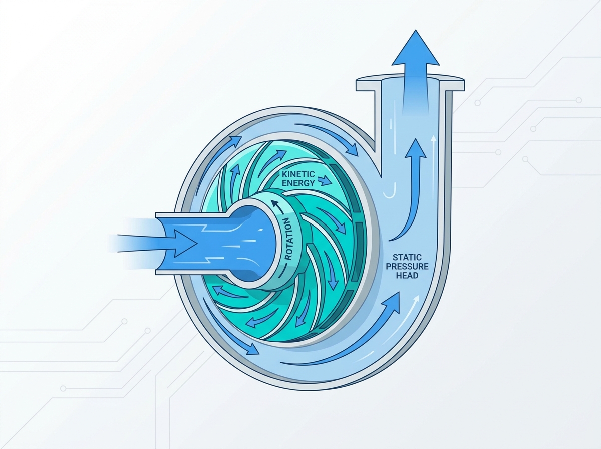
Manufacturers configure these pumps into several distinct structural types. You must match the physical configuration to your specific flow rate, pressure demands, and available floor space.
End-Suction Pumps: These represent the most common industrial configuration. Fluid enters horizontally through the end and exits vertically. They offer tremendous versatility and cost-effectiveness. You will find them dominating general facility water transfer, cooling towers, and commercial HVAC systems.
Split-Case Pumps: Heavy-duty applications require split-case designs. The casing literally splits along a horizontal plane. Maintenance crews can remove the top half to inspect the entire rotating assembly. They do this without ever disturbing the massive suction and discharge pipes. You evaluate them primarily for high-flow, continuous-duty municipal or industrial scenarios.
Multistage Pumps: Some systems require immense discharge pressure. Expanding the physical footprint is often impossible. Multistage pumps solve this by stacking multiple impellers sequentially on a single shaft. The first impeller builds pressure and feeds the second. The second compounds it and feeds the third. Boiler feed systems and high-pressure reverse osmosis plants rely heavily on multistage configurations.
Vertical In-Line & Sump Pumps: Tight mechanical rooms create spatial headaches. Vertical in-line pumps mount directly into the piping like a valve. They require zero dedicated floor space. Vertical sump pumps operate differently. The motor sits safely above ground. A long shaft drops the impeller down into submerged pits for sub-surface fluid extraction.
Different industries define operational success through completely different metrics. Understanding these nuances ensures you specify the right machine for the right job.
Water and wastewater treatment facilities prioritize continuous operation above all else. Success here means preventing clogs. Raw sewage contains rags, plastics, and dense biological solids. Engineers specify recessed or vortex impellers to handle these challenges. These specialized designs create a localized whirlpool. The whirlpool pulls solids safely through the casing without them ever touching the vanes.
Chemical and petrochemical processing plants face extreme hazards. Fluid containment is an absolute necessity. A minor leak can trigger catastrophic fires or environmental disasters. Procurement teams enforce strict adherence to API 610 or ANSI standards. These standards dictate heavier casing thicknesses and specialized bearing housings. Engineers must rigorously verify chemical compatibility between the pumped fluid and the internal elastomers.
The food and beverage sector demands absolute purity. Bacteria cannot have any place to hide. Sanitary guidelines rule this industry. Pumps must feature highly polished 316L stainless steel interiors. They must support clean-in-place (CIP) protocols. This allows operators to flush hot caustic chemicals through the system safely. Successful deployment requires strict compliance with FDA and EHEDG design regulations.
Mining and heavy industry present a brutal mechanical environment. Pumping highly abrasive slurries destroys standard metals in hours. Success requires exceptionally robust construction. You must specify hard-metal impellers. Replaceable wear plates become mandatory. These sacrificial components take the brunt of the abrasive damage. Maintenance teams can replace them quickly to protect the main, expensive casing.
Selecting the correct model requires precise mathematical evaluation. Guesswork leads directly to system failures. You must follow a strict engineering logic to shortlist viable options.
Map Flow Rate vs. Head Pressure: You first determine how much fluid you need to move (capacity) and how much resistance it faces (head). You plot these numbers to create a system curve. You then lay this curve over manufacturer performance graphs. The goal is to select a model where your system curve intersects the pump curve at its Best Efficiency Point (BEP).
Evaluate Cavitation Risks: This remains the most critical evaluation metric. You must analyze Net Positive Suction Head (NPSH). As fluid enters the impeller eye, pressure drops. If pressure falls below the fluid's vapor pressure, the liquid boils instantly. Bubbles form and violently collapse against the metal vanes. This destroys impellers rapidly. Net Positive Suction Head Available (NPSHa) must always exceed the manufacturer's Required value (NPSHr).
Adjust for Specific Gravity and Viscosity: Standard performance curves assume you are pumping clear water. Thicker or heavier fluids behave differently. Heavy chemicals require more torque to move. You must scale your motor horsepower upwards to handle higher specific gravities. Failing to adjust this calculation results in immediate motor burnout.
Apply Regulatory Compliance Lenses: You must filter your shortlist through industry standards. General industrial applications lean on ISO specifications. Chemical processing heavily favors ANSI standards for dimensional interchangeability. High-risk oil and gas deployments strictly require API certified construction. Match the standard to your facility risk profile.
Even perfectly sized systems fail if implemented incorrectly. You must manage several critical physical risks during installation and daily operation.
Energy consumption represents a massive ongoing liability. Over-sizing a system forces the motor to draw unnecessary power. It also forces the equipment to operate away from its Best Efficiency Point. Operating off BEP causes severe internal vibration. You can mitigate this energy drain by utilizing Variable Frequency Drives (VFDs). A VFD dynamically adjusts motor speed to match exact system demands. This prevents wasted energy and reduces mechanical stress.
Installation realities often ruin excellent engineering. Pipe strain serves as the most common deployment failure. Installers sometimes force misaligned heavy pipes to bolt onto the pump flanges. This forces the entire casing to twist. The internal shaft bends, and bearings fail within days. You must independently support all piping. Furthermore, you must grout the baseplate perfectly to the concrete floor to absorb operational vibrations.
Maintenance and wear require proactive management. Bearings and mechanical seals serve as the most predictable failure points. You should never wait for them to break. Implement routine condition monitoring. Technicians can use vibration analysis tools to track internal health. A spike in high-frequency vibrations indicates impending bearing wear. Identifying this early prevents catastrophic, unplanned downtime.
Sourcing a centrifugal pump requires balancing initial capital expenditure against long-term operational stability. You cannot rely on physical dimensions alone. You must dive deeply into fluid dynamics, material science, and mechanical limitations to ensure success.
We recommend engineers take strict, methodical actions before purchasing. First, verify the exact properties of your fluid under operating temperatures. Second, calculate your available NPSH accurately to guarantee you avoid cavitation. Third, clearly define the compliance standards required by your specific industry sector.
Do not hesitate to leverage expert guidance. Compile your precise flow rates, head pressures, and fluid characteristics. Contact our engineering and sales team today with these system parameters. We will provide a tailored technical evaluation and a detailed quote to secure your facility's operational future.
A: A centrifugal pump uses a spinning impeller to generate continuous flow. It works best for thin, low-viscosity fluids like water. A positive displacement pump traps a fixed volume of fluid and forces it through the discharge pipe per revolution. It is highly effective for thick, highly viscous fluids or applications requiring precise metering.
A: No. Running dry causes immediate and severe mechanical damage. The pumped fluid acts as a crucial lubricant and coolant for the internal mechanical seals and bearings. Without fluid, immense heat builds up rapidly, destroying the seals. You must use specialized self-priming variants if temporary dry running is unavoidable.
A: Cavitation occurs when the fluid pressure inside the suction line drops below the liquid's vapor pressure. The fluid instantly boils, forming tiny vapor bubbles. As these bubbles hit the high-pressure zone of the rotating impeller, they collapse violently. This rapid implosion sends shockwaves that pit and destroy metal surfaces.
A: You find the BEP by analyzing the manufacturer's performance curve graph. The BEP is the specific point on the curve where the pump transfers energy to the fluid most efficiently. Operating as close to this point as possible minimizes internal vibration, reduces energy consumption, and extends overall component lifespan.